netborplastik
|
21 Ekim 2020
1. Lowering the Pipes:
HDPE100 pipes should be taken to a suitable stockpile where they will be least affected by weather conditions depending on the time until they are laid.
When lowering the pipes in the stock area, it is recommended to use cloth ropes / ropes with appropriate strength, taking into account the weight of the hanging pipe. It is not appropriate to use chains or steel ropes during lowering.
 Figure-1: Suspending and unloading from two points with cloth rope
2. Field Storage: In the area where the pipes are stored, the ground should be leveled to prevent surface scratches and hard objects sinking, and a pile should be formed on 4-5 rows of planks (10x10) with equal spacing depending on the diameter and load to be lined on the base.
-min.jpg)
Figure-2: Creating a pipe stack (stack) on the plank
Stack Height (H) should be between 1.5m and 2.5m depending on the pipe pressure class (wall thickness) and storage time. In irrigation projects, it is recommended that the pile height should not exceed 1.5 meters in PN6-PN8 pressure classes. Management specifications are taken as basis for higher pressure classes.
-min.jpg)
Figure-3: Pile Height (H) in Pipes
Side wedge supports should be nailed to horizontal planks in a way to prevent pipe slippage while forming pile. After removing the pipe from the pile, if there is a gap in the bottom row that may slip, the places of the wedge supports should be updated.
In case the pipe stack height (H) exceeds the limits and there is a shortage of space, the 2nd floor can be created by taking support between the 2 piles from the ground. However, it is not recommended unless it is compulsory, as it will need to be well supported against slipping and collapsing.
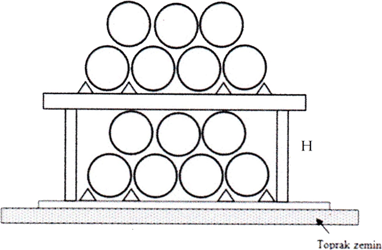
Figure-4: Creating a Folded Stack
The pipes should be prevented from being thrown on the ground or dropped suddenly on the ground or on the pile while lifting, and should be protected against impacts.
3.Line Laying of Pipes and Trench Excavation: Pipes should not be transported by dragging while laying in the field, should not be pulled in contact with the ground while welding on the edge of the trench and while lowering into the ditch, appropriate transport and pulling tools should be used.
Pipes are first lined up on the edge of the ditch in accordance with the project in open land flooring such as irrigation, drinking water transmission line. The lined pipes are welded to each other by the selected welding method.
.jpg)
Picture-1: Welding of the pipes lined up on the route of the trench with Butt Welding.
In the application, depending on the availability of the land, pipes can also be welded on the edge of the excavated ditch.
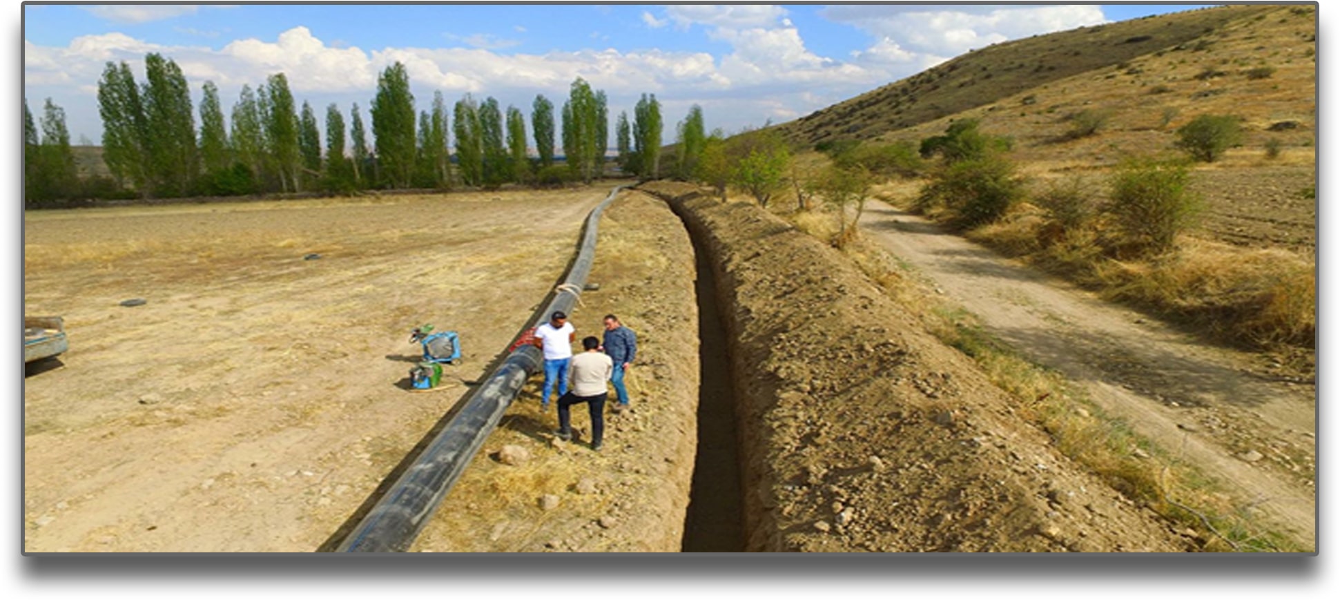
Picture-2: Arranging and welding pipes on the excavated ditch edge
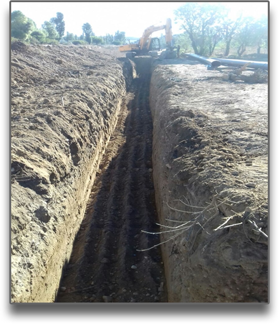
Image-3: Trench Excavation
4. Connection of Pipes (Butt Welding): The combination of PE100 pipes is mostly done in the field by butt welding. Butt welding is done by heating the pipe fronts with a heating iron, melting them and pushing them together under pressure. All butt welding process should be done according to ISO 21307 and / or equivalent standards.


Image-4,5,6: Placing and fixing the pipes to the welding machine
Necessary precautions should be taken in order not to be affected by external environment conditions (rain, dust, etc.) while welding the pipes. The calibration of the welding machine heater iron thermocouples must have been done in an accredited laboratory just before their first welding in the field. There should be no abrasion, scratches and damage on the iron teflon surfaces. Welds made with damaged teflon surfaces (preventing uniform melting without gaps on the forehead) or defective thermocouples (since the welding temperature is never known to be correct) will eventually cause problems.
ISO 21307: 2017 Plastics pipes and fittings - Butt fusion jointing procedures for polyethylene (PE) pipes and fittings used in the construction of gas and water distribution systems.
5. Lowering the Pipes into the Trench: A ditch should be dug in accordance with the condition of the trench floor and necessary support measures should be taken. On weak grounds, reinforcement and support measures should be taken depending on the depth of the trench and the required slope angles should be given.
In other types of soils, administration specifications should be adhered to depending on the depth and characteristics of the trench. Ground water should be drained, if any, during laying on the trench floor. Pipes should be placed in the trench after the trench bottom is completely flattened, cushion material is laid and compacted.


The operations performed are as shown in the pictures;
- The trench base is prepared,
- The bottom of the trench is flattened,
- Stone dust is laid on the bottom of the trench (H = 15 cm),
- Stone dust on the floor is compressed,
- Cushion material is compressed,
- Laying / unloading the pipe on the pillow material,
- Filling the pipe.
- Suction cup connection to the peaks where the slope changes in the line direction to prevent the air pocket.
- Prevention of dirt and dust entering the pipe at the pipe-fittings points welded in the field.
If the trench foundation is not strong and a smooth surface cannot be formed on rotten grounds, foundation improvement should be done. A trench foundation should be formed, not less than H = 20 cm, by pressing rock and rock under the bedding layer. The backfill should be placed in the trench without any gaps.

.jpg)
6. Tightness Test: If the pipeline to be tested is too long, it is divided into sections so that the test can be controlled and leak points can be detected quickly. The assembly of the armature (valve, suction cup, pump, etc.) on the line is completed (Flanges are tightened and sealed).
The line to be tested is filled with water from a suitable point. Air outlet is provided from the upper point (suction cups, if any, on the line) as elevation. For a successful leak test, make sure that the air in the line is completely evacuated when filling the water.
For the correct determination of the pressure value reached during the test, the manometer should be placed at the lowest point (where the static pressure will be the highest) as elevation. The leakage test will be made according to the pipe nominal pressure and the specifications of the administration.
After the line is completely filled with water, the outlet valves are closed and within 10 minutes the line is pressurized to the nominal pressure of the pipe. Some administrations may request that the value of this pressure be increased to a value between 10-50% above the nominal pressure. However, this surplus pressure demand is reduced by multiplying by a reduction factor in cases where air is used as the test fluid, the line is open and exposed to sunlight for a long time.
The pump continues to operate to stabilize the pressure for 10 minutes after the pipe reaches its nominal pressure. After that, the pumping process is stopped and the pipeline is observed for 30 minutes. In case of a drop in pressure, water is added to the nominal pressure value.
Subsequently, if there is a deviation of less than 5% of the nominal pressure for 90 minutes, the line is considered tight.
During the test, water leaks, dripping, etc. on the line, welds, flange connections. If it is seen, the test is interrupted, leaks are repaired or leaky armature connections are tightened and then the test is restarted.
Testing with air is not recommended for safety reasons (the potential to throw the filling on the top of the pipe, the side of the pipe in explosive parts, the temperature of the compressed air increases by + 30-35 C and the temperature inside the pipe increases even at the air inlet points without cooling and decreases the pressure resistance of the pipe. .